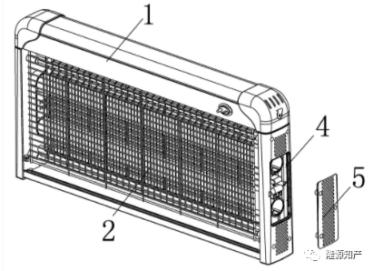
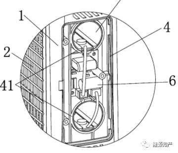
This case involves a mosquito killer. The mosquito killer is in the shape
of a hollow rectangular parallelepiped, with a lamp tube inside for attracting
mosquitoes, and an electric shock net for killing mosquitoes on the outside. In
this case, the patentee's improvement on the mosquito killer lies in opening an
inspection window on the side of the mosquito killer, and replacing the
fluorescent tube with an LED lamp, which facilitates maintenance and improves
the light source. The patentee initiated two patent infringement lawsuits
against multiple defendants for the patent in 2018, claiming 300,000 yuan and
500,000 yuan respectively. However, because the patent was completely invalid,
the basis for the lawsuit was lost, and both lawsuits were dismissed. Here we
focus on the use of evidence in the invalidation process of this case.
Case introduction
The patent number of this case is: CN201420659511.X, and the patent name
is: a new type of mosquito killer.
Rights request
1. A novel mosquito killer, which comprises a main frame (1) and an
electric shock net (2) covered in front of it, the electric shock net is
electrically connected with a high-voltage power supply board arranged in the
main frame, and a mosquito trap is arranged behind the electric shock net. The
lamp tube (3) is characterized in that: the main frame (1) is also provided with
an inspection window (4), which is covered by a decorative cover (5) to hide the
inspection window (4). ) is installed with a control circuit board (6) and is
electrically connected with the mosquito trapping lamp (3), the mosquito
trapping lamp (3) includes a light guide tube (31) and an LED light-emitting
board that is snapped into it. (32), the end face of the mosquito trapping lamp
(3) is located in the inspection window (4).
2. A kind of novel mosquito killer according to claim 1, is characterized
in that:
The light guide tube (31) is made of acrylic or PVC or PC material, and a
card slot (33) is arranged in the tube, and the LED light-emitting board (32) is
snapped and fixed in the card slot (33).
3. A kind of novel mosquito killer according to claim 1 or 2, is
characterized in that:
The LED light-emitting board (32) comprises a substrate (321) and a
plurality of LED lamp beads (322) distributed thereon in a uniform array, the
substrate is connected with a power cord with a plug, and the plug is inserted
on the control circuit board (6) It is electrically connected to the socket
(61).
4. A kind of novel mosquito killer according to claim 1, is characterized
in that:
There are two mosquito trapping lamps (3), which are symmetrically
distributed up and down behind the electric shock net (2).
5. A new type of mosquito killer according to claim 1, characterized in
that: the inspection window (4) is provided with a positioning frame (41), and
the mosquito trapping lamp (3) can be axially mounted. It is inserted and fixed
on the positioning frame (41).
6. A new type of mosquito killer according to claim 1 or 5, characterized
in that: the decorative cover (5) is detachably fixed on the inspection window
(4) through a buckle.
7. A novel mosquito killer according to claim 1 or 5, characterized in
that: the decorative cover (5) is detachably fixed on the inspection window (4)
through screws.

Attached map of the patent involved

invalid program
Regarding this patent, the petitioner filed a request for invalidation with
the Patent Reexamination Board on November 17, 2018. The reasons include: Claims
1-2 do not possess the inventive step specified in Article 22, paragraph 3 of
the Patent Law, and request to declare the claims of this patent 1-2 was
invalid, and the petitioner submitted evidence 1-5. Within one month, the
petitioner supplemented evidence 6-10 and requested to declare claims 1-7
invalid. All the evidences are as follows:
Evidence 1: The Chinese utility model patent with the authorization
announcement number CN2O3897100U;
Evidence 2: The Chinese utility model patent with the authorization
announcement number CN201682919U;
Evidence 3: The Chinese utility model patent with the authorization
announcement number CN2817438Y;
Evidence 4: The Chinese utility model patent with the authorization
announcement number CN202991672U;
Evidence 5: The Chinese invention patent application with the application
publication number CN103196048A.
Evidence 6: The Chinese utility model patent with the authorization
announcement number CN2648819Y;
Evidence 7: The Chinese invention patent application with the application
publication number CN1O2620161A;
Evidence 8: The Chinese utility model patent with the authorization
announcement number CN203517463U;
Evidence 9: Chinese invention patent application with application
publication number CN1O2308780A;
Evidence 10: The Chinese utility model patent with the authorization
announcement number CN202738664U.
The petitioner believes that: 1) the patent claim 1 is relative to the
combination of evidence 6, evidence 5 and conventional technical means in the
field, or the combination of evidence 6 and evidence 7 and the conventional
technical means in the field, or evidence 6, evidence 8 The combination with
conventional technical means in the field, or the combination of evidence 1,
evidence 5, and evidence 2 with conventional technical means in the field, or
the combination of evidence 1, evidence 5, and evidence 3 with conventional
technical means in the field, or evidence 1. The combination of Evidence 5 and
Evidence 4 with conventional technical means in this field does not possess the
inventive step stipulated in Article 22(3) of the Patent Law. 2) The additional
technical features of the dependent claims 2-7 are disclosed by evidence or are
common knowledge in the field. Therefore, on the basis that claim 1 does not
possess an inventive step, the dependent claims 2-7 also do not possess an
inventive step.
Rights request
Claim 1: Regarding the invalid request made by the petitioner, the
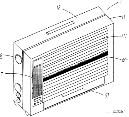
collegiate panel of this case believes that: Evidence 6 discloses a grid
mosquito trap, and specifically discloses: the mosquito trap housing 1 composed
of the front cover 11 and the box body 12, The high-voltage power grid 2
installed in the box body 12 divides the box body into two cavities 121 and 122,
the front and the rear. A number of fluorescent lamps 3 are set up in the rear
cavity 122. The circuit board 4 is respectively connected with the high-voltage
grid 2 and a plurality of fluorescent tubes 3; a fluorescent tube exchange cover
8 is provided on one side of the rear cavity 122 of the box body to facilitate
the insertion and removal of the fluorescent tubes 3. The front cover 11 is
provided with an outer layer safety net 111; and when replacing the fluorescent
tube 3, without disassembling the case 12, the fluorescent tube can be directly
opened to exchange for the cover 8, which improves the safety of the user.
The "mosquito trap housing" in the evidence 6 corresponds to the "main
frame (1)" of this patent, the "high voltage grid 2" corresponds to the
"electric shock net (2)" in this patent, and the "fluorescent lamp 3"
corresponds to the The "mosquito trap lamp (3)" of this patent, "the mouth
covered by the exchange cover 8" corresponds to the "access window (4)" of this
patent, and the "exchange cover 8" corresponds to the "decorative cover (5)" of
this patent )”, since the “control circuit board 4” of evidence 6 is
respectively connected to the high-voltage grid 2 and several fluorescent lamps
3, therefore, the “control circuit board 4” both corresponds to the “control
circuit board (6)” of this patent, and Corresponding to the "high-voltage power
supply plate", the "portion between the support plates 35" corresponds to the
"installation groove" of this patent. It can be seen from Figures 1 and 2 of
Evidence 6 that the high-voltage grid 2 is covered in front of the housing, and
the fluorescent lamps 3 are arranged behind the high-voltage grid 2; As can be
seen from the function of the lamp tube exchange cover 8 described in 6, the end
face of the fluorescent lamp tube 3 is located at the opening covered by the
exchange cover 8 .
The difference between the technical solution defined in claim 1 of this
patent and the technical content disclosed in evidence 6 is that the types of
mosquito traps are different, and the location of the control circuit board is
different. In this patent, the control circuit board is installed in the
inspection window (4). , the mosquito trapping lamp tube (3) includes a light
guide tube (31) and an LED light-emitting board (32) snapped into it, while the
fluorescent lamp tube used in the evidence 6, and the control circuit board 4 is
not arranged in the Inside the inspection window.
Based on the above-mentioned distinguishing technical features, it can be
seen that the actual technical problem to be solved by this patent is how to
facilitate the maintenance of the control circuit and improve the luminous
effect of the mosquito trapping lamp.
Regarding the above-mentioned distinguishing technical features, evidence 5
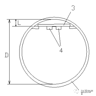
discloses a wide-angle light-emitting LED lamp, and specifically discloses:
including a round tube diffuser lampshade 1 and lamp caps 2 arranged at both
ends of the round tube diffuser lampshade 1, and the round tube diffuser
lampshade 1. The position where the inner circle diameter of the cross section
is less than one third of the diameter is provided with the active heat
dissipation substrate 3, that is, the farthest point from the active heat
dissipation substrate 3 to the inner circle of the cross section of the round
tube diffuser lampshade 1 as shown in FIG. 1 and FIG. 2 The distance L is less
than one-third of the diameter D of the inner circle of the cross-section of the
circular tube diffuser lampshade 1, the active heat dissipation substrate 3 is
provided with LED4, and a power drive component 5 is provided between the lamp
head 2 and the active heat dissipation substrate 3; The power drive component 5
is replaced by an integrated circuit, which is directly integrated on the active
heat dissipation substrate 3. The "round tube diffuser lampshade 1" in evidence
5 corresponds to the "light guide" of this patent, and the "active heat
dissipation substrate 3 and LED4" corresponds to the "LED light-emitting board
(32)" of this patent, and "power drive component 5" corresponds to the "control
circuit board" of this patent. It can be seen from Figures 1 and 2 of Evidence 5
that the active cooling The substrate 3 and the LED 4 are fixed in the round
tube diffuser lampshade 1 by means of snaps. From the above record of evidence
5, it can be seen that evidence 5 also discloses an LED light tube, and the
structure of the LED light tube is the same as that of the mosquito trapping
light tube in claim 1 of this patent, both of which are a built-in LED
light-emitting tube. Compared with the fluorescent lamp, the LED tube obviously
has the effect of softer and uniform light emission, low energy consumption and
long service life as the LED lamp in this patent has. Those skilled in the art
are facing the evidence When the mosquito trap of 6 is not soft and uniform
enough to emit light, which is not conducive to attracting mosquitoes, high
energy consumption and short service life, there is an incentive to replace the
LED tube in evidence 5 with the fluorescent tube in evidence 6 to overcome
evidence 6. the above-mentioned defects. Since one end of the fluorescent tube
of the evidence 6 is provided with a replacement cover, and the power drive part
5 of the evidence 5 is arranged at one end of the LED lamp, when a person
skilled in the art combines the evidence 6 with the evidence 5, that is, the
replacement cover in the evidence 6 is located at the cover 8. When the
fluorescent tube is replaced with an LED tube, the power source driving part 5
is correspondingly arranged at the exchange cover 8. By opening the exchange
cover 8, the power source driving part 5 and the LED lamp tube can be repaired,
so the claim 1 can be clearly obtained. "The control circuit board is installed
in the access window (4)" in the technical feature.
To sum up, those skilled in the art can obviously obtain the technical
solution of claim 1 of this patent on the basis of evidence 6 and evidence 5.
Therefore, claim 1 of this patent does not have substantive features and
progress, and does not have Article 22 of the Patent Law. Creativity under
paragraph 3.

Evidence 6

Evidence 5
Claim 2: On the basis of claim 1, it is further defined that "the light
guide tube (31) is made of acrylic or PVC or PC material, and a card slot (33)
is provided in the tube, and the LED light-emitting board ( 32) The buckle is
fixed in the slot (33)."
The petitioner believes that the additional technical features of the
dependent claim 2 can be obtained by those skilled in the art based on evidence
5, evidence 8 or evidence 7 in combination with common knowledge.
The collegiate panel believes that: as can be seen from Figures 1 and 2 of
Evidence 5, the circular tube diffuser lampshade 1 of Evidence 5 is provided
with a card slot, and the active heat dissipation substrate card and LED4 are
buckled and fixed in the card slot. Therefore, the evidence 5 discloses the
feature in the subordinate claim 2 that "a card slot (33) is provided in the
tube, and the LED light-emitting board (32) is snapped and fixed in the card
slot (33)", although evidence 5 discloses "Place the substrate in a single plane
or two in an inverted V shape, fix and completely cover it in a plastic or glass
tubular lampshade" (see paragraph [0017] of the description of evidence 5,
Figure 1), It is not clear that the tubular lampshade is made of acrylic or PVC
or PC material, but the above-mentioned materials are all well-known plastic or
glass materials in the art. It is a conventional choice for those skilled in the
art to select the above-mentioned materials as the material of the light pipe.
No creative work is required, and unexpected technical effects have not been
achieved. Therefore, on the basis that claim 1 does not possess the inventive
step, the dependent claim 2 does not possess the inventive step stipulated in
Article 22(3) of the Patent Law.
Claim 3: On the basis of claim 1 or 2, it is further defined that "the LED
light-emitting board (32) comprises a substrate (321) and a plurality of LED
lamp beads (322) distributed thereon in a uniform array, and the substrate is
connected with Power cord with plug, the plug is inserted into the socket (61)
on the control circuit board (6) to be electrically connected to it".
The petitioner believes that the additional technical features of the
dependent claim 3 can be obtained by those skilled in the art based on evidence
5, evidence 8 or evidence 7 in combination with common knowledge.
The collegial panel believes: Refer to Figures 1-3 of Evidence 5. Evidence
5 discloses that the LED light-emitting board includes an active heat
dissipation substrate 3 and several LEDs 4 distributed thereon, although
Evidence 5 does not disclose the uniform distribution of LED lamp beads in an
array. However, the above differences are all conventional technical means in
the art, and the adoption of such technical means has not achieved unexpected
technical effects. Therefore, on the basis that claim 1 or 2 does not possess
the inventive step, the dependent claim 3 also does not possess the inventive
step stipulated in Article 22(3) of the Patent Law.
Claim 4: Dependent claim 4 further defines on the basis of claim 1 that
"there are two mosquito trapping lamps (3), which are symmetrically distributed
up and down behind the electric shock net (2)".
The petitioner believes that the additional technical features of the
dependent claim 4 can be obtained by those skilled in the art on the basis of
evidence 1, evidence 2 or evidence 6 in combination with common knowledge.
The collegial panel believes that: Evidence 6 discloses that two
fluorescent tubes are arranged up and down behind the high-voltage power grid 2
(see Figure 1 of Evidence 6). Although evidence 6 does not disclose the
symmetrical arrangement of the two fluorescent tubes, in order to adjust and
optimize the lighting Anti-mosquito effect, the two lamps are symmetrically
arranged, which is a conventional technical means for those skilled in the art,
which does not require creative work, and does not achieve unexpected technical
effects, therefore, claim 1 does not have creativity Dependent claim 4 also does
not possess the inventive step stipulated in Article 22(3) of the Patent
Law.
Claim 5: Dependent claim 5 further defines on the basis of claim 1 that
"the access window (4) is provided with a positioning frame (41), and the
mosquito trapping lamp (3) can be inserted and fixed in the axial direction. on
the spacer (41)".
The petitioner believes that the additional technical features of the
dependent claim 5 can be obtained by those skilled in the art on the basis of
evidence 6 in combination with common knowledge, or are common knowledge in the
field.
The collegiate panel believes that: in order to enable the lamp tube to be
stably installed on the mosquito killer, it is easy for those skilled in the art
to set up a positioning frame so that the mosquito trapping lamp tube can be
axially inserted and fixed on the positioning frame, which does not require
creative work. Therefore, on the basis that claim 1 does not possess the
inventive step, the dependent claim 5 also does not possess the inventive step
stipulated in Article 22(3) of the Patent Law.
Claims 6 and 7: Dependent claims 6 and 7 areOn the basis of requirements 1
or 5, it is further defined that "the decorative cover (5) is detachably fixed
on the inspection window (4) by means of snaps" and "the decorative cover (5) is
detachably fixed on the inspection window (4) by means of screws. Access window
(4)".
The petitioner believes that the additional technical features of the
subordinate claim 6 belong to the common knowledge in the field, or are
disclosed by evidence 2. Additional technical features of the dependent claim 7
are common knowledge in the field or disclosed by evidence 4 .
The collegiate panel believes that: since the exchange cover in Evidence 6
needs to be removed when it needs to be exchanged for maintenance, the exchange
cover needs to be detachable, and snaps or screws are commonly used in this
field. Those skilled in the art can easily think of using the above method to
realize the detachable connection of the exchange cover. Therefore, on the basis
that claim 1 or 5 is not inventive, the dependent claims 6 and 7 also do not
have the provisions of Article 22, paragraph 3 of the Patent Law. creativity.
Thus, all claims 1-7 of this patent are declared invalid.
Summarize
This case is a very typical case of patent infringement and patent
invalidity defense. Although the patentee holds a valid patent, he has to admit
the fact that the patented invention involved in this case has a low height, and
has added maintenance to the mature mosquito killer. The mouth and cover plate
are not complicated improvements, and changing the fluorescent tubes to LED lamp
beads is also a conventional improvement brought about by the development of
science and technology, and there is no surprise. In addition, there are certain
problems in the drafting of the claims of the patent involved. The drafting of
several dependent claims is too simple, and their additional technical features
can be easily found in the prior art. The petitioner's preparations were also
quite adequate, and 10 pieces of evidence were prepared, and finally all invalid
results were obtained.
Therefore, for the technical solutions of key protection, the drafting of
the claims should include as many parallel technical solutions as possible,
refine the technical features, and make the invalidation procedure more
difficult; the patentee should evaluate the patent before initiating an
infringement lawsuit. Depending on the level of technical content, if necessary,
make an evaluation report or a search report, and do not fight unprepared
battles.